A professional automotive wiring diagram editor. Build accurate harness diagrams, trace circuits, generate bills of materials, and export print-ready documentation — entirely in the browser.
Logging In
12VoltWiz uses magic link authentication — no password required. Enter your email, click the link in the email, and you're in.
Magic Link Sign-In
- 1Open 12voltwiz.vercel.app in your browser.
- 2Click Sign In and enter your email address.
- 3Check your inbox for a message from 12VoltWiz. Click Sign in in that email.
- 4You are signed in automatically and returned to the editor.
The magic link expires after a few minutes. If it doesn't work, return to the sign-in screen and request a new one. Check your spam folder if the email doesn't appear within 30 seconds.
Your account and subscription are tied to your email address. Always use the same email to access your plan and cloud-saved projects.
Interface Overview
The editor is divided into four primary areas:
| Area | Purpose |
|---|---|
| Toolbar | File management, undo/redo, view settings, wire defaults, and vehicle info. |
| View Tabs | Switch between Canvas, BOM, Wiring Table, Cutlist, and Labels. |
| Canvas | The diagram workspace — place components and draw wires here. |
| Right Panel | Shows the Library when nothing is selected; switches to the Inspector when a component or wire is selected. |
| Status Bar | Live component and wire counts, color swatches, grid/snap toggles, and zoom level. |
Toolbar
Every action in the toolbar is an icon button. Hover any button to see its tooltip. Buttons that are active — Grid on, Snap on, vehicle data entered, canvas detached — glow amber.

File Group
| Button | Action |
|---|---|
| New | Creates a blank project. Prompts for confirmation if the canvas contains unsaved content. |
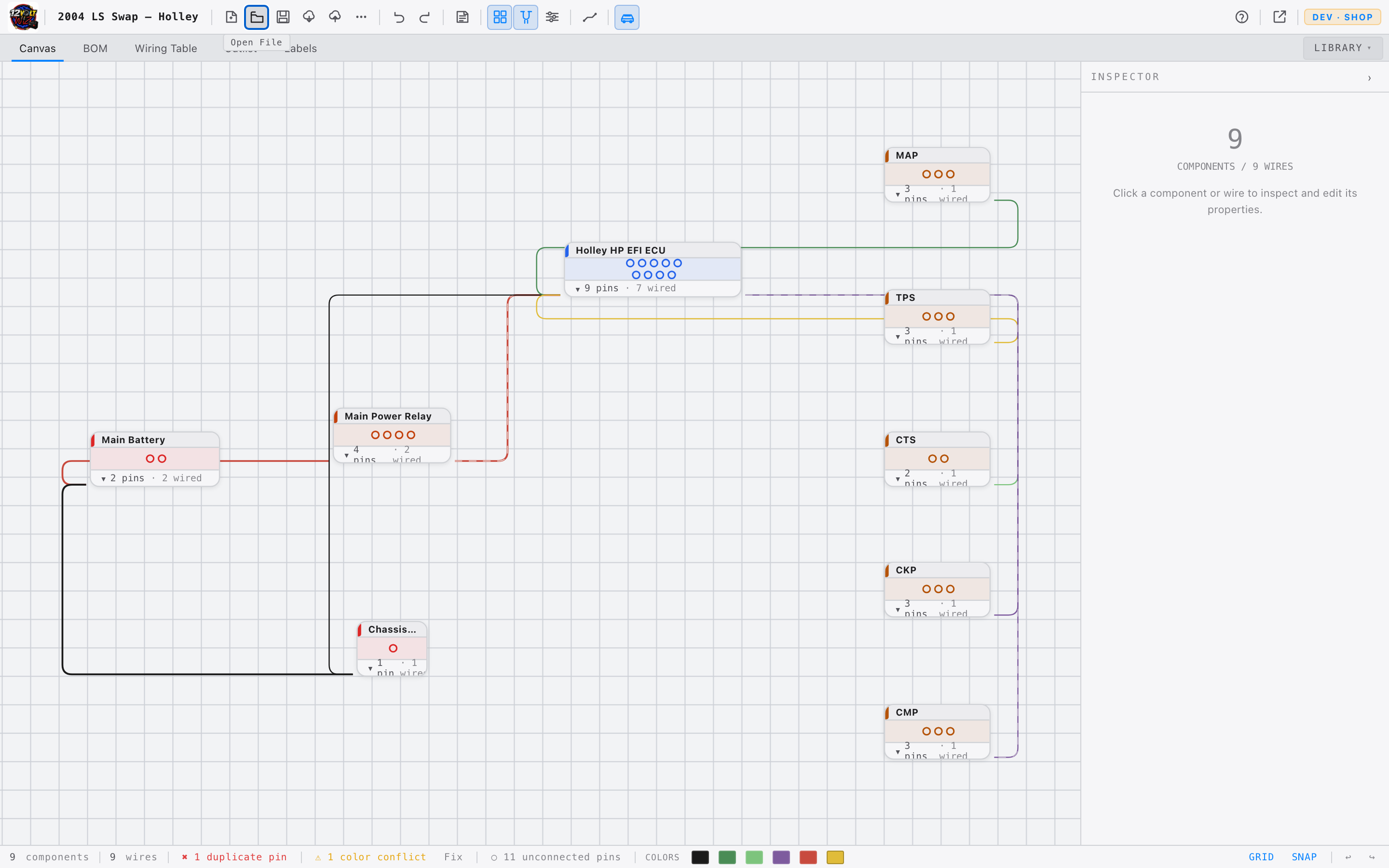
| Open | Opens a file picker to load a .12vw project file from your computer. |
| Save | Downloads the current project as a .12vw file. Shortcut: ⌘S |
| More (···) | Reveals a menu: Save As ⌘⇧S, Export PNG, Export PDF, Export CSV, New Swap Wizard. |
Edit Group
| Button | Action |
|---|---|
| Undo | Reverts the last action. ⌘Z |
| Redo | Re-applies an undone action. ⌘⇧Z |
View Group
| Button | Action |
|---|---|
| Grid | Toggles the background grid. Glows amber when on. Shortcut: G |
| Snap | Snaps components to the grid when moving them. Glows amber when on. Shortcut: S |
| View Settings | Opens a popover with controls for grid line width, grid opacity, snap size, measurement units (AWG/ft or mm²/m), background image upload, and theme. |
Wire Defaults
The wire icon opens a popover to set the defaults applied to every new wire drawn:
| Setting | Options |
|---|---|
| Color | SAE code — BLK, RED, GRN, WHT, BLU, YEL, ORN, BRN, PNK, GRY, TAN… |
| Gauge | 8, 10, 12, 14, 16, 18, 20, 22, or 24 AWG |
| Signal Type | Signal, Power, Ground, Output |
Vehicle
The car icon opens a popover to record the vehicle's information. This data appears on exported PDFs and CSV files. The button glows amber when any vehicle data is present.
| Field | Example |
|---|---|
| Year | 2002 |
| Make | Chevrolet |
| Model | Camaro |
| Engine | LS1 5.7L |
| Transmission | 4L60E |
| ECU | Holley Terminator X |
Pop Out — Dual Monitor
The Pop Out button detaches the canvas into a separate browser window that you can move to a second monitor. Both windows stay in sync — drag a component in the pop-out and the wiring table in the main window updates immediately.
The pop-out window includes its own Inspector panel. Click any component or wire in the pop-out and the Inspector appears on the right, the same as in the main window.
Typical dual-monitor layout: canvas on the large screen, main window (tabs, library, inspector) on the laptop or second screen. The button glows amber while the canvas is detached. Close the pop-out window to bring the canvas back to the main window.
Account
When logged in, your email address and plan appear in the top-right of the toolbar. Click to reveal a menu with your plan name and a sign-out option.
On a paid plan, two additional buttons appear in the toolbar file group: Save to Cloud and Open from Cloud. See Files & Export for details.
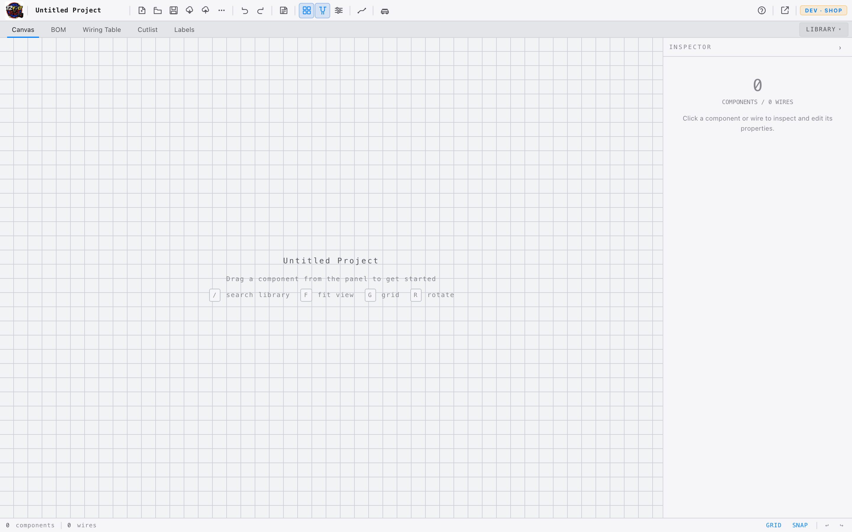
Canvas
The canvas is the diagram workspace. Components are placed here, wires are drawn between their pins, and the diagram is arranged into a readable schematic.
Navigation
| Action | How |
|---|---|
| Zoom in / out | Scroll wheel |
| Pan | Middle-click drag, or hold Space and left-click drag |
| Select | Left-click on any component or wire |
| Multi-select (rubber-band) | Click and drag on empty canvas to draw a selection rectangle |
| Add to selection | Hold Shift and click additional components |
| Deselect | Click on empty canvas |
| Move a component | Left-click drag it to the new position |
Placing Components
There are two ways to place a component from the Library:
- Drag and drop — click and drag a component from the Library onto the canvas and release where you want it.
- Double-click — double-click any component in the Library to place it at the center of the viewport. Consecutive double-clicks stagger each placement slightly so components don't stack.
Drawing Wires
- 1Hover over a component. Small pin handles — dots at connection points — appear along its edge.
- 2Click and drag from a pin handle to begin drawing a wire.
- 3Drag to another component's pin handle and release to complete the connection.
- 4The wire is created with the current Wire Default settings for color, gauge, and signal type.
Configure Wire Defaults before drawing a run of wires. All new wires inherit those settings — you can still change any individual wire in the Inspector afterward.
Right-Click Menu
Right-clicking any component opens its context menu:
| Option | Action |
|---|---|
| Info | Displays the component's part number, connector family, and pin count. |
| Rotate | Rotates the component to 0°, 90°, 180°, or 270°. |
| Mark NC pin | Opens the NC pin selector — mark individual pins as No-Connect. NC pins render as a small dot instead of a live handle. |
| Delete | Removes the component and all wires connected to it. |
Right-clicking a wire shows a separate menu:
| Option | Action |
|---|---|
| Delete Wire | Removes only that wire. Undo with ⌘Z. |
Component Labels
Canvas nodes display the component's brand and model name only. Spec details (voltage, capacity, amperage) are in the Inspector — keeping the canvas readable at any zoom level.
Pin Handles
Each component shows small pin handles at its connection points. Drag from a handle to start a wire. Click a handle (without dragging) to trace or identify it — connected pins highlight the full net; open pins highlight only that handle so you can locate it on a busy canvas. Click again to clear.
Some overland components show a small gold diamond instead of a round handle on certain pins. These are CAN bus ports — they are shown for reference but cannot be wired in the diagram. Hover the diamond for details.
Deleting
Select any component or wire, then press Delete or Backspace. To delete only a wire without selecting it first, right-click the wire → Delete Wire. Removing a component also removes all of its connected wires.
Multi-Select
To select multiple components at once, click and drag on empty canvas to draw a rubber-band selection rectangle. Any node the rectangle touches is included. You can also hold Shift and click individual nodes to add them to the selection one at a time.
With multiple nodes selected you can:
- Drag them all together as a group
- Delete them all at once with Delete
- Right-click the selection → Group to create a named Branch Group
- Right-click the selection → Save as Template to save the sub-diagram for reuse
Branch Groups
A Branch Group visually groups related components — such as all the connectors on a single engine loom branch — under a named label. It draws a bounding rectangle around the members and shows the branch name, making the diagram easier to read and navigate.
- 1Rubber-band drag to select 2 or more components on the canvas.
- 2Right-click anywhere on the selection. A prompt appears: "Group N nodes as branch."
- 3Type a name for the branch — for example
Injector Bank AorPassenger Firewall. The name is optional; leaving it blank names the group Branch. - 4Press Enter or click Group. A labelled bounding box appears around the selected nodes.
Moving the branch bounding box moves all its members together. You can still drag individual members independently — the branch box resizes automatically to fit. Right-click the branch box to rename it, refit the bounding box, or ungroup.
When a branch group is selected, the Inspector shows a Bundle Diameter calculator that reads the gauge of every wire in the group and recommends split loom and Techflex F6 conduit sizes. See Tools & Calculators.
Waypoints
A Waypoint node (available in the Library) routes wires around obstacles without creating a functional component. Wires connect to it like any other pin, letting you bend paths into right angles or specific routes.
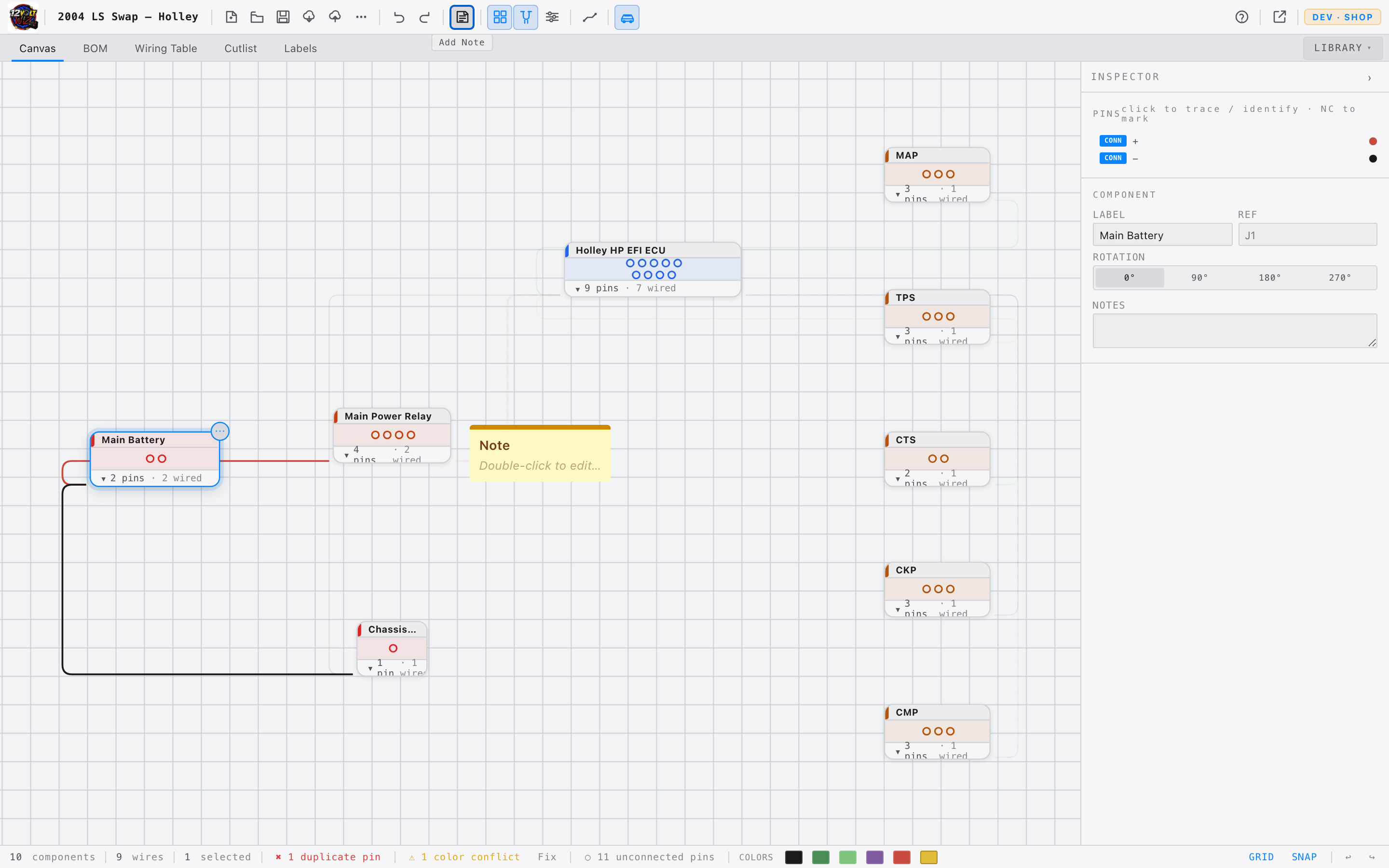
Annotations — Sticky Notes
Add a sticky note to the canvas to record assumptions, callouts, or to-dos directly on the diagram. Notes are purely visual — they are excluded from the BOM, wiring table, cutlist, validation, and every electrical calculation, so they never affect your part counts or checks.
- 1Click Add Note in the toolbar. A note drops at the center of the current view.
- 2Double-click the note to edit its title and body text.
- 3Choose one of five colors (yellow, blue, green, pink, gray) in the Inspector, and drag any edge of the note to resize it.
Library Panel
The Library opens as a panel from the LIBRARY button in the tab bar. It has three tabs — Components, Catalog, and Templates — and contains every component available for placement on the canvas.
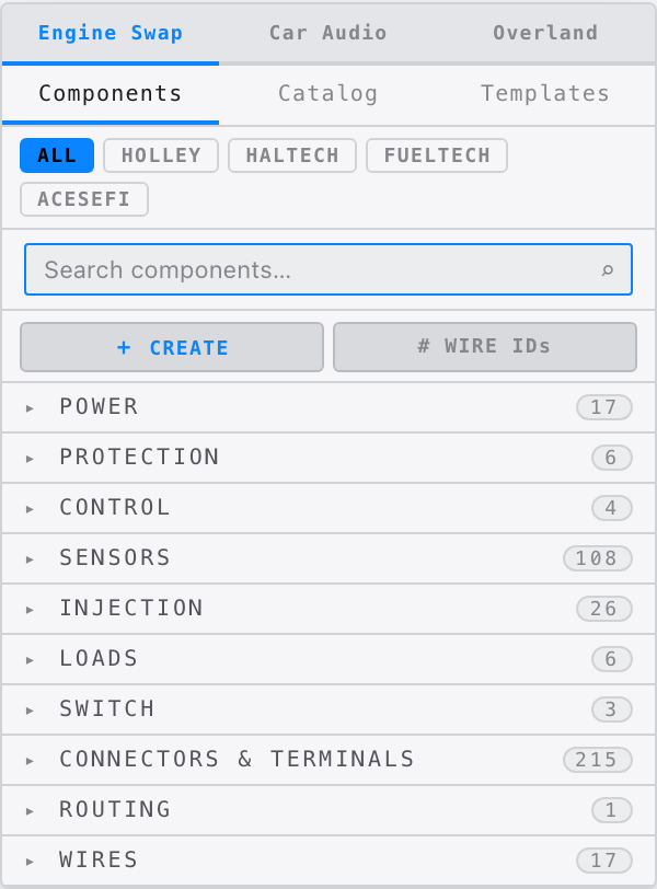
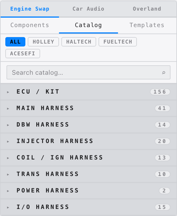
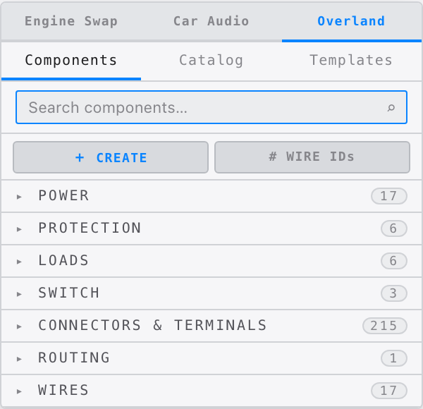
Library Modes
Three mode buttons at the top of the Library switch the panel between disciplines:
| Mode | Shows | Plan Required |
|---|---|---|
| Engine Swap | Full library — ECU kits, harnesses, sensors, injectors, connectors, power, and Catalog tab | Free and above |
| Car Audio | Amplifiers, subwoofers, speakers, crossovers + shared Power / Connector / Load / Switch groups | Builder and above |
| Overland | Batteries, DC-DC chargers, solar, inverters, monitoring, trailer wiring + shared Power / Connector / Load / Switch groups | Builder and above |
The selected mode is saved automatically and restored the next time you open the app.
Categories — Engine Swap Mode
Overland Library BUILDER PLAN
Switch to Overland mode to access the mobile power library. All pinout data is sourced from official manufacturer installation manuals.
| Group | What's Included |
|---|---|
| Trailer Wiring | SAE J2863 7-pin and 4-pin flat vehicle connectors and plugs, brake controller, breakaway switch and battery, running/stop/reverse lights |
| Batteries | LiFePO4 generics (100/200/300Ah), configurable battery, dual-battery, battery bank (2–4 parallel), Battle Born BB10012 / BB10012H (heated), Dakota Lithium 100Ah |
| DC-DC Chargers | Victron Orion-Tr Smart 30A, Orion XS 50A, Renogy DCC30S, Sterling BB1230/BB1260, Kisae DMT1230, REDARC BCDC1225D/1240D/1250D, Blue Sea ML-ACR 7622 |
| All-in-One BMS | REDARC Manager30 (DC-DC + MPPT + 240VAC mains) |
| Alternator Regulators | Wakespeed WS500 (13-pin CAN-bus) |
| Solar | Rigid panels (100/200/400W), flexible, Victron SmartSolar MPPT 100/30 + 100/50, Renogy Rover 40A, MC4 pair / T-branch / inline fuse, Go Power 100W + 200W folding |
| Inverters | Generic configurable (600–5000W), fixed 1/2/3kW, Victron MultiPlus 12/2000VA + 12/3000VA, Kisae SW1220, shore power inlet TT-30 |
| Shore Power | Progressive Dynamics PD9245CV (45A), PD9260CV (60A) |
| Monitoring | Victron SmartShunt 500A, REDARC BSEN500, Renogy 500A monitor, Victron Cerbo GX |
| Distribution | Configurable fuse block, pos/neg distribution blocks, Blue Sea 5026 fuse block |
| Van Loads | Winch, roof vent fan, compressor fridge, diesel heater, water pump, LED puck/strip, 120V AC outlet, USB outlet, 12V outlet |
Manufacturer Documentation
When a branded Overland component is selected, the Inspector shows links to the official installation manual and product page. Click PDF to open the manual in a new tab, or Product Page to go to the manufacturer's website.
| Brand | Products | PDF Manual | Product Page |
|---|---|---|---|
| Victron Energy | SmartSolar MPPT 100/30 + 100/50, Orion-Tr Smart 30A, Orion XS 50A, MultiPlus 12/2000VA + 12/3000VA, SmartShunt 500A, Cerbo GX | ✓ | ✓ |
| Wakespeed | WS500 Alternator Regulator | ✓ | ✓ |
| Kisae | DMT1230 DC-DC Charger, SW1220 Inverter | ✓ | ✓ |
| Sterling Power | BB1230, BB1260 DC-DC Chargers | ✓ | ✓ |
| Battle Born | BB10012H Heated Battery | ✓ | ✓ |
| Blue Sea Systems | ML-ACR 7622, 5026 Fuse Block | ✓ | ✓ |
| Progressive Dynamics | PD9245CV, PD9260CV Shore Converters | ✓ | ✓ |
| REDARC | BSEN500 | ✓ | ✓ |
| REDARC | Manager30, BCDC1225D/1240D/1250D | — | ✓ |
| Battle Born | BB10012 (standard) | — | ✓ |
| Dakota Lithium | 12V 100Ah | — | ✓ |
| Renogy | DCC30S, Rover 40A, 500A Monitor | — | ✓ |
| Go Power | 100W + 200W Folding Solar | — | ✓ |
REDARC PDF manuals are not linked directly — their download portal requires authentication. Use the product page link to access documentation from REDARC's website.
Configurable Components ⚙
Components marked with ⚙ in their subtitle have adjustable properties. Select the component and edit its values in the CONFIGURATION section of the Inspector. Pins update dynamically as you change the settings.
| Component | What You Can Set | Pin Layout |
|---|---|---|
| Fuse Block 2–12 circuits |
Number of circuits (2–12); individual fuse rating per circuit (A) | IN (left) · GND (bottom) · C1–CN (right, one per circuit) |
| Positive Distribution Block 2–8 posts |
Number of output posts (2–8) | IN (left) · O1–ON (right) |
| Negative Distribution Block 2–8 posts |
Number of output posts (2–8) | IN (left) · O1–ON (right) |
| Battery (Generic) | Voltage (6V / 12V / 24V / 48V); capacity (Ah); chemistry (AGM / GEL / LiFePO4 / Lead Acid / Lithium) | B+ (right) · B− (right) |
| Battery Bank 2–4 in parallel |
Number of batteries (2–4); voltage; capacity; chemistry | BAT1+..N+ (left) · BAT1−..N− (right) · BUS+/BUS− (top) |
| Inverter (Generic) | Continuous wattage; type (Pure Sine / Modified Sine) | DC+ / DC− (left) · AC-HOT / AC-NEU / AC-GND (right) |
| Winch | Rated pull (lb); brand name | BATT+ / BATT− (left) · IN / OUT (right) · REMOTE / GND (bottom) |
The Dual Battery (Parallel) component is a fixed 6-pin node — BAT1+, BAT1−, BAT2+, BAT2−, BUS+, BUS− — and is not configurable. Use Battery Bank if you need 3 or 4 batteries in parallel with dynamic pin counts.
Connector Families
The connector library covers the most common families used in automotive harness work. Each connector includes plug and receptacle variants with verified housing and terminal part numbers.
| Family | Variants in Library |
|---|---|
| Deutsch DT | 2, 3, 4, 6, 8, 12 pin — plug and receptacle |
| Deutsch DTM | 2, 3, 4, 6, 8, 12 pin — plug and receptacle |
| Deutsch DTP | 2, 3, 4 pin — plug and receptacle |
| TE Superseal 1.5 | 1, 2, 3, 4, 6 pin — plug and receptacle |
| Delphi Metripack 150 | Common 2–8 pin housings |
| Delphi Weatherpack | 1, 2, 3, 4, 6 pin tower and shroud |
| Bosch EV1 (Jetronic) | Injector — plug and receptacle |
| Bosch EV6 (USCAR) | Injector — plug and receptacle |
| Bosch LSU 4.9 | Wideband O2 sensor connector |
Using ECU Kits
- 1Expand ECU Kits in the Library panel.
- 2Expand a brand — Holley, Haltech, FuelTech, AcesEFI, and others.
- 3Select the specific kit to see its included harnesses and connectors.
- 4Drag the main harness node onto the canvas to place the system.
Search
The search bar at the top of the Library filters all components by name, part number, or brand. Results update as you type.
Search by part number — e.g. 558-103 — to find an exact harness immediately. Search by connector family — e.g. SuperSeal — to browse all matching connectors.
Templates
The Templates tab stores sub-diagrams you've saved for reuse — for example, a dual-fan relay setup, a 3-relay nitrous stage, or any other wiring block you find yourself building repeatedly.
Templates require a User plan or higher and are saved to your account so they're available across devices.
Saving a template
- 1Rubber-band select the components you want to save (2 or more).
- 2Right-click the selection and choose Save as Template.
- 3Give the template a name, pick a category, and add an optional description.
- 4Click Save. The template appears in the Templates tab immediately.
Placing a template
- Drag a template from the Templates tab onto the canvas to place it at a specific position.
- Double-click a template to place it at the center of the viewport.
Every node and wire in the placed template gets fresh IDs — placing the same template multiple times creates independent copies with no shared state.
Templates are organized by category (Power, Ignition, Fans & Cooling, Nitrous, etc.) matching the component library. Use the search bar in the Templates tab to find a template by name or description.
Inspector Panel
When a component or wire is selected, the right panel switches from the Library to the Inspector, where properties can be viewed and edited.
Connector Reference Photos
For known connector families, a reference photo appears at the top of the Inspector when that connector is selected. The photo is accompanied by a colored family badge — green for Weatherpack, blue for Deutsch DT/DTM, purple for Delphi GT150, and so on — making it easy to visually confirm you have the right connector in hand before crimping.
Photos appear for standalone connectors dragged from the Library and for connector ends on expanded harness nodes. Families covered include: Weatherpack (GM), Deutsch DT / DTM / DTP, TE Superseal 1.5, Metripack 150, Delphi GT150, Bosch EV1 / EV6 injector, and Bosch LSU4.9 wideband.
Wire Inspector
Click any wire to select it and expose these properties:
| Property | Description |
|---|---|
| Color | SAE wire color code — BLK, RED, GRN, WHT, etc. |
| Stripe | Optional secondary stripe color. Displayed as BASE/STRIPE, e.g. WHT/BLU. |
| Gauge | Wire gauge in AWG (or mm² when metric mode is active). |
| Signal Name | What the wire carries — e.g. TPS Signal, Injector 1 GND. |
| Circuit Name | Circuit or net identifier — e.g. A14, C-112. |
| Routing | Orthogonal (right-angle bends) or Curved. |
| Start Terminal | Terminal type at the source end — ring terminal, butt splice, ferrule, or fork/spade. Appears in the BOM automatically. |
| Finish Terminal | Terminal type at the destination end. Same options as Start Terminal. |
Set Start Terminal and Finish Terminal on each wire instead of placing ring terminal nodes on the canvas. The canvas stays clean and the BOM still counts every terminal automatically.
Component Inspector
Click any component — connector, sensor, harness end — to see its details:
| Field | Description |
|---|---|
| Reference Photo | Physical connector photo with family badge — shown for known connector families. |
| Family | Connector family name, e.g. Delphi Metripack 150. |
| Housing P/N | Manufacturer part number for the connector housing. |
| Terminal P/N | Part number for the crimp terminals. |
| Seal P/N | Part number for wire seals, where applicable. |
| Signals / Pins | Full pin table — pin label, kind (power/ground/signal/CAN), and connection status (CONN / OPEN). Click any connected pin row to trace its net. |
| Manufacturer Docs | Branded Overland components show a PDF button (opens the official installation manual) and a product page link. |
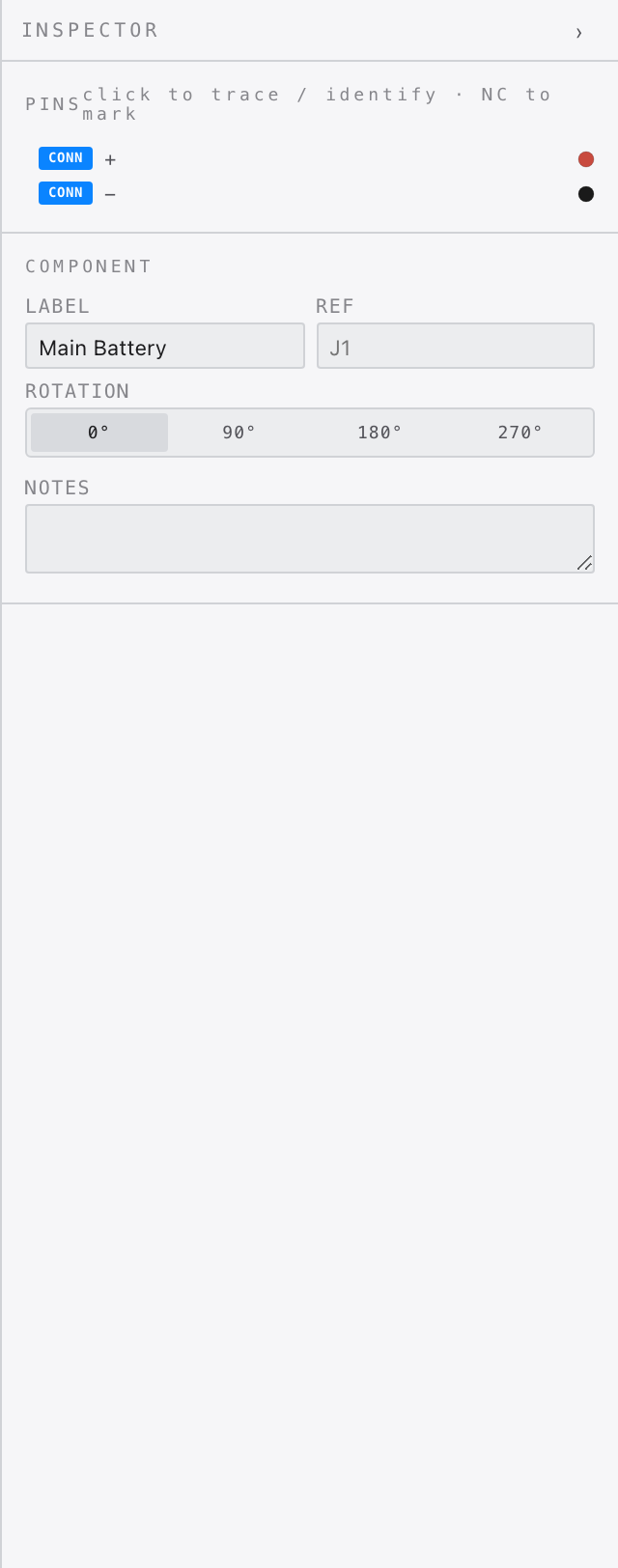
Pin Table — Tracing and NC Marking
The PINS section lists every pin on the selected component. Each row shows the connection status and a label.
- CONN — pin has a wire. Click the row to trace the entire connected net. Click again to clear.
- OPEN — pin has no wire. Click the row to identify it — the pin handle on the canvas highlights so you can locate it at a glance. Click again to deactivate. Click NC to mark it as intentionally No-Connect.
- NC (marked) — intentionally unused. Click the dot on the canvas or the row in the Inspector to identify it. Click ✕ NC to restore it.
- CAN (gold badge) — CAN bus port. Shown for reference only; cannot be wired in the diagram. Refer to the manufacturer's installation manual for CAN network wiring.
Battery Bank
When a battery node is wired to one or more other batteries, the Inspector shows a BATTERY BANK section with the computed topology and electrical result:
| Topology | How wired | Result |
|---|---|---|
| PARALLEL | B+ to B+, B− to B− | Same voltage, capacity adds — e.g. 2× 12V 100Ah = 12V 200Ah |
| SERIES | B+ of one to B− of next | Voltage adds, same capacity — e.g. 2× 12V 100Ah = 24V 100Ah |
The DRC short-circuit check is suppressed for battery-to-battery wires. A separate error fires only if the same pair is wired both in series and parallel simultaneously.
Wire Inspector — Temperature Derating
The Wire Gauge Calculator and Fuse Sizing section both show an ℹ icon next to ampacity values. Hovering it displays:
SAE J1292 bundled ampacity: 60°C wire, 40°C ambient. Derate for high-temp locations. Verify with wire manufacturer datasheet.
Ampacity values in the calculator are based on bundled wiring at standard ambient temperature. For engine bay or exhaust-adjacent runs, use a heavier gauge than recommended or consult your wire manufacturer's derating chart.
The Signals table in the component Inspector is read-only reference data. To edit a wire's color or gauge, click the wire itself and make changes in the wire Inspector.
Harness Nodes
A Harness Node represents a multi-connector wiring harness — for example, a Holley Terminator X kit harness. It is a special component with expandable connector ends that expose individual pins for wiring.
Controls
| Button | Action |
|---|---|
| ⊞ Expand | Reveals all connector ends as individual nodes with exposed pins ready for wiring. |
| ⊟ Collapse | Hides the connector ends to reduce visual clutter in the diagram. |
| ↕ Vertical | Arranges connector ends stacked top-to-bottom. |
| ↔ Horizontal | Arranges connector ends spread left-to-right. |
Typical Workflow
- 1Drag the harness from the Library onto the canvas.
- 2Click ⊞ to expand the connector ends.
- 3Use ↕ or ↔ to arrange the layout to match your physical routing.
- 4Draw wires from exposed pins to sensors, power sources, or other connectors.
Selecting an expanded connector end in the Inspector shows its complete signal list with pin numbers, signal names, wire colors, and gauges — all sourced from official manufacturer documentation.
Tools & Calculators
Context-sensitive calculators appear automatically in the Inspector when the right component is selected. They use the diagram's own data — wire length from node positions, gauge already on the wire, load already entered — so there is nothing extra to configure.
Wire Gauge / Ampacity Calculator
Select any wire and scroll to the WIRE GAUGE CALCULATOR section in the Inspector.
- 1Enter the Load (amps) the wire will carry continuously.
- 2Enter the Run length (ft) — one-way distance.
- 3The calculator shows the recommended AWG, current capacity headroom, and voltage drop at load.
- 4Click Apply to update the wire gauge in the diagram.
| Output | What it means |
|---|---|
| Recommended AWG | Smallest gauge that safely carries the load with <3% voltage drop at the given length. |
| Capacity | Maximum continuous ampacity of the selected gauge per SAE J378 (chassis wiring). |
| Voltage drop | Millivolt drop at full load across the run length. Critical for sensor reference circuits. |
Always measure the actual routed length, not the straight-line distance. Add 15–20% for bends and slack. A 3 ft run under the hood might route 5 ft through the firewall and along the frame.
Fuse & Relay Sizing Assistant
Select any fuse or relay node. The FUSE / RELAY SIZING section appears in the Inspector.
- 1Enter the Load (amps) the protected circuit will draw.
- 2The assistant calculates the correct fuse rating using the 125% rule (NEC/SAE standard): fuse = load × 1.25, rounded up to the next standard size.
- 3For loads over 20A, a Bosch relay recommendation appears with its part number.
| Standard fuse sizes | |
|---|---|
| ATC / ATO (blade) | 5 · 7.5 · 10 · 15 · 20 · 25 · 30 · 40A |
| Mini (ATM) | 5 · 7.5 · 10 · 15 · 20 · 25 · 30A |
| Maxi | 20 · 30 · 40 · 50 · 60 · 70 · 80A |
Bundle Diameter Calculator
Select a Branch Group node (created by selecting multiple wires and using the right-click menu). The BUNDLE DIAMETER section appears in the Inspector.
The calculator reads the gauge of every wire in the bundle, computes the packed-circle outer diameter using standard wire OD data, and recommends correctly-sized conduit:
| Output | Description |
|---|---|
| Bundle OD | Calculated outer diameter of the bundled wires in inches and mm. |
| Wire breakdown | Count of wires per gauge in the bundle. |
| Split loom | Recommended split loom size (nominal ID) with a buy quantity. |
| Techflex F6 | Recommended Techflex F6 expandable braid size with a buy quantity. |
The recommended sizes assume a 40% fill ratio — the industry standard that leaves room for flex and future additions. If you are sleeving an existing tight loom, go one size up.
Validation & DRC
12VoltWiz continuously checks the diagram for electrical errors and flags them in the Status Bar. Checks run automatically as you draw — nothing to trigger manually.
Gauge Warning Badges
When a wire connected to a power or ground pin is thinner than 14 AWG, an orange ⚠ badge appears at the midpoint of that wire on the canvas.
- Hover the badge to see the full warning — component name, pin, current gauge, and recommended minimum (e.g. "Battery 1 · B+: 18 AWG on power pin — use ≥14 AWG").
- Click the badge to select that wire and open it in the Inspector, where you can change the gauge immediately.
Status Bar DRC Indicators
All active errors and warnings appear as labelled buttons in the Status Bar. Each button shows a count and can be clicked to select the affected wires or components for inspection.

| Indicator | Severity | Meaning |
|---|---|---|
| ✖ duplicate pin | Error | The same pin has more than one wire connected. Only specific multi-connect pins (battery studs, bus bars, ground studs) allow multiple wires. |
| ✖ short circuit | Error | A power pin and a ground pin are directly wired together with no load in between. |
| ⚠ gauge warning | Warning | A wire on a power or ground pin is thinner than 14 AWG, or a wire is undersized for its fuse rating. Click to select all affected wires. |
| ⚠ floating power | Warning | A power or ground pin exists on a component that has other wires, but that specific pin has nothing connected to it. |
| ⚠ color conflict | Warning | The same SAE color is used more than once on a small component. Click Fix to auto-assign unique colors. |
| ✖ battery bank conflict | Error | The same battery pair is wired both in series and parallel simultaneously — this short-circuits one cell. Remove one connection to resolve. |
Battery terminals, ground studs, chassis grounds, power studs, and bus bar terminals accept multiple ring terminals by design. These pins are exempt from the duplicate pin check and can have as many wires as needed.
Ampacity values are based on SAE J1292 — bundled wiring at 60°C wire rating, 40°C ambient. For engine bay or high-heat installations, derate the recommended gauge. The ℹ icon in the Wire Gauge Calculator shows this note inline.
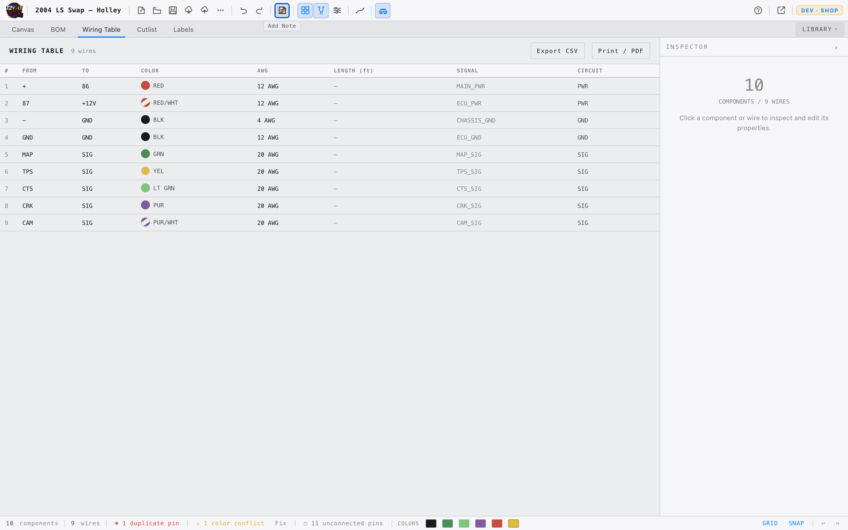
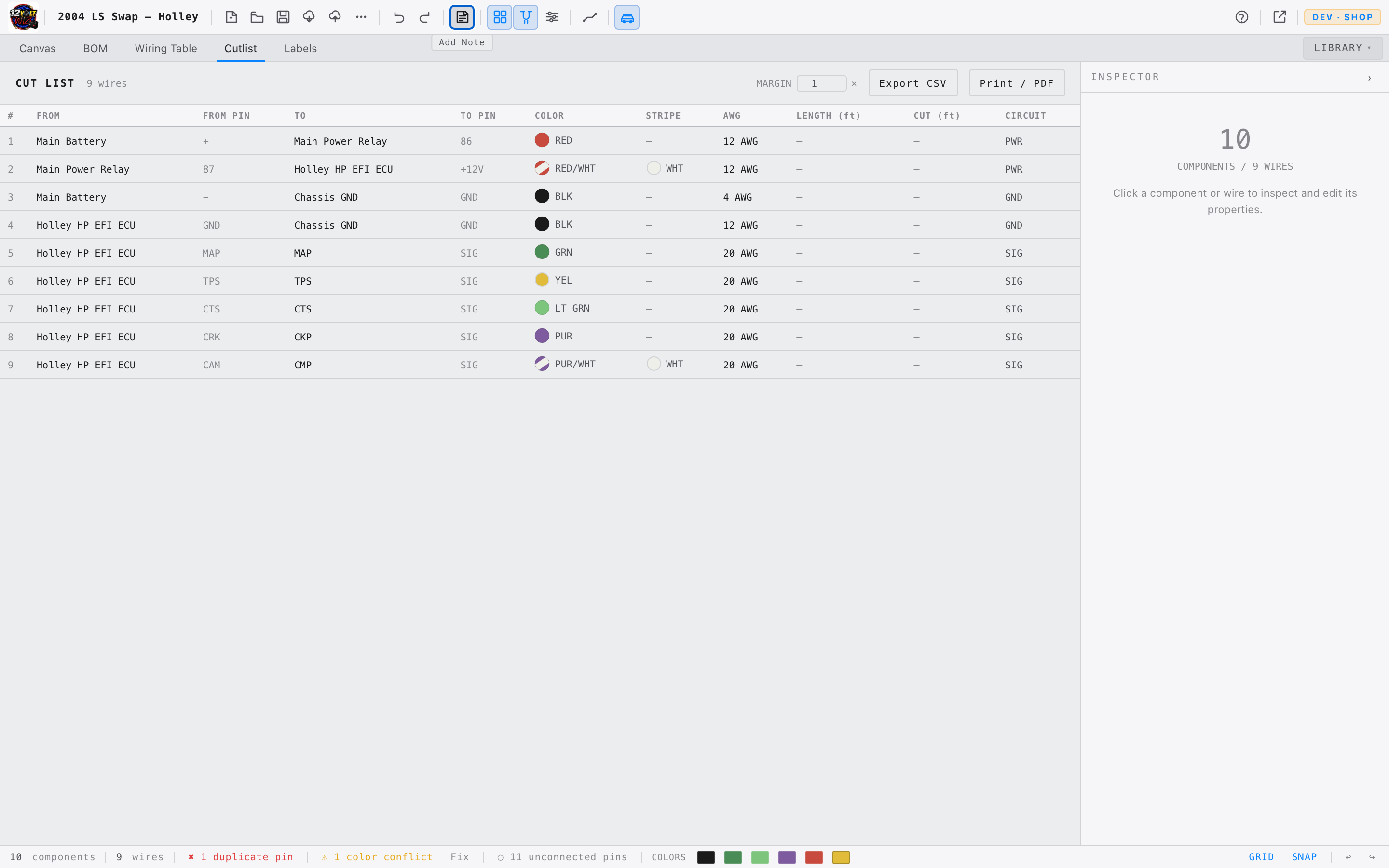
Tabs
The tab bar below the toolbar switches between five views of the project. All output tabs update automatically as the canvas changes — switching tabs never modifies the diagram.
Net Tracing
Net tracing visually highlights circuits through the diagram without changing anything. Three trace modes are available — all non-traced elements dim to make the active circuit easy to follow.
Net Trace — Follow a Circuit
Click any wire on the canvas. All wires electrically connected in the same net — the same continuous circuit — highlight together. Non-traced wires dim. Click the wire again or click empty canvas to clear.
Use net tracing to verify continuity. If two points should share a circuit, click one wire and confirm both highlight. If they don't, an open connection exists somewhere in that path.
Pin Trace — Start from a Specific Pin
Two ways to trace from a specific pin rather than a wire:
- Inspector pin row — select a component, then click any CONN pin row in the PINS section. The full net connected to that pin highlights.
- Canvas handle — hover a component to reveal its pin handles, then click a handle (without dragging). The net highlights from that pin outward. A small accent ring marks the active handle.
Click the same pin again, or click empty canvas, to clear the trace.
Color Trace — Highlight by Wire Color
The Status Bar shows a color swatch for every SAE color in use. Click a swatch to highlight all wires of that color across the entire diagram. Click the swatch again or the ✕ button to clear.
Status Bar
| Element | Description |
|---|---|
| Component count | Total nodes on the canvas. |
| Wire count | Total wires drawn. |
| DRC indicators | Error and warning badges appear when the diagram has issues — see Validation & DRC. |
| Color swatches | One per SAE color in use. Click to trace all wires of that color. |
| GRID / SNAP | Quick toggle buttons, same as the toolbar. |
| ↩ / ↪ | Undo and redo buttons. |
Files & Export
Local Save
Projects save as .12vw files — a JSON-based format storing the complete diagram, vehicle information, and settings. The file downloads to your computer.
| Action | Location | Shortcut |
|---|---|---|
| Save | Toolbar → Save button | ⌘S |
| Save As | Toolbar → ··· More → Save As | ⌘⇧S |
| Open | Toolbar → Open button | — |
12VoltWiz does not auto-save. Press ⌘S frequently. Closing the browser tab without saving will discard unsaved changes.
Cloud Save USER PLAN AND ABOVE
On a paid plan, projects can also be saved to your account and opened from any browser — no file management required.
- 1Click the cloud save button in the toolbar (cloud with up arrow). The project is saved to your account immediately.
- 2To open a cloud project, click the cloud open button (cloud with down arrow). Your saved projects appear in a list — click any row to load it.
Cloud save and local .12vw save are independent. A cloud-saved project is not automatically downloaded to your computer, and a locally-saved file is not automatically uploaded to the cloud. Use both for peace of mind.
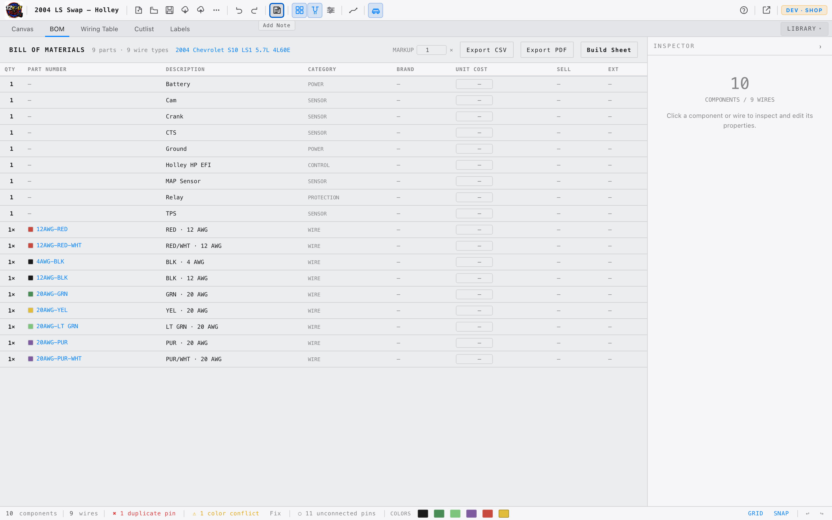
Export Formats
Diagram exports (PNG, PDF) are found in Toolbar → ··· More. The BOM PDF and the combined Build Sheet are generated from buttons in the BOM tab; the wiring-table and cutlist CSVs export from their own tabs.
| Format | Contents | Best For |
|---|---|---|
| PNG | High-resolution image of the canvas diagram. | Documentation, presentations, sharing. |
| Print-ready PDF of the wiring diagram. | Shop floor reference, customer deliverables. | |
| CSV | Wiring table or cutlist as a spreadsheet. | Importing into other tools, parts ordering. |
| BOM PDF | Bill of Materials as a print-ready PDF, with optional unit costs, markup, and totals. | Quotes, customer invoices, parts ordering. |
| Build Sheet | One combined PDF — the wiring diagram, the full BOM, and the wiring table together. | A complete shop-floor package in a single document. |
The Build Sheet button in the BOM tab produces a single hand-off document: the diagram on a landscape page, then the BOM and the full wiring table on following pages. One click, one print dialog, one PDF.
Opening a File
- 1Click the Open button in the toolbar (folder icon).
- 2Select a
.12vwfile from your computer. - 3If unsaved changes exist, a confirmation prompt appears before the file loads.
Keyboard Shortcuts
| Action | Mac | Windows / Linux |
|---|---|---|
| Save project | ⌘S | Ctrl+S |
| Save As | ⌘⇧S | Ctrl+Shift+S |
| Undo | ⌘Z | Ctrl+Z |
| Redo | ⌘⇧Z | Ctrl+Shift+Z |
| Delete selected node or wire | Delete | Delete |
| Delete selected (alternate) | Backspace | Backspace |
| Rotate selected | R | R |
| Fit diagram to view | F | F |
| Toggle grid | G | G |
| Toggle snap to grid | S | S |
| Open Library | / | / |
| Deselect / close menu | Esc | Esc |
| Zoom in / out | Scroll | Scroll |
| Pan the canvas | Middle-drag | Middle-drag |
Mac uses ⌘ (Command) and ⇧ (Shift). On Windows and Linux, Ctrl replaces ⌘. Single-letter shortcuts (R, F, G, S, /) are identical on every platform.
Browser Support
12VoltWiz is a modern web application. It requires a current browser to function correctly.
| Browser | Support | Notes |
|---|---|---|
| Chrome | ✓ Full | Recommended. All features work. |
| Edge | ✓ Full | Recommended. All features work. |
| Firefox | ✓ Full | All features work on recent versions. |
| Safari 16.2+ | ✓ Full | macOS Ventura / Sonoma and later. |
| Safari < 15.4 | ⚠ Partial | Pop Out canvas will not work. |
| Mobile browsers | ✗ Unsupported | Canvas interactions require a mouse. |
If you open 12VoltWiz in an unsupported or outdated browser, an amber warning bar will appear at the top of the screen describing what may not work. You can dismiss it, but switching to Chrome or Edge will resolve the issue entirely.
If you are on a Mac and prefer Safari, update to macOS Ventura or later to get full support. Alternatively, install Chrome — it is free and takes two minutes.
SAE Wire Colors
12VoltWiz uses SAE J1128 standard color codes throughout — the same codes found in factory service manuals and professional harness documentation.
Stripe Notation
Many wires carry a base color with a contrasting stripe. Both are set independently in the wire Inspector. The notation is always BASE/STRIPE:
| Code | Meaning |
|---|---|
| WHT/BLU | White wire with a blue stripe |
| BLK/RED | Black wire with a red stripe |
| GRN/YEL | Green wire with a yellow stripe |
| RED | Solid red — no stripe |
Wire colors in the 12VoltWiz component library are sourced directly from manufacturer documentation — Holley, Haltech, FuelTech, AcesEFI, and others — and match the actual wire colors in those harnesses.